SolidWorks Design & Engineering ProjectsThis section showcases my SolidWorks projects, where I apply engineering design principles to create detailed 3D models, assemblies, and technical drawings. My work emphasizes accuracy, manufacturability, and iterative design, with a focus on developing functional components that can be prototyped and tested.
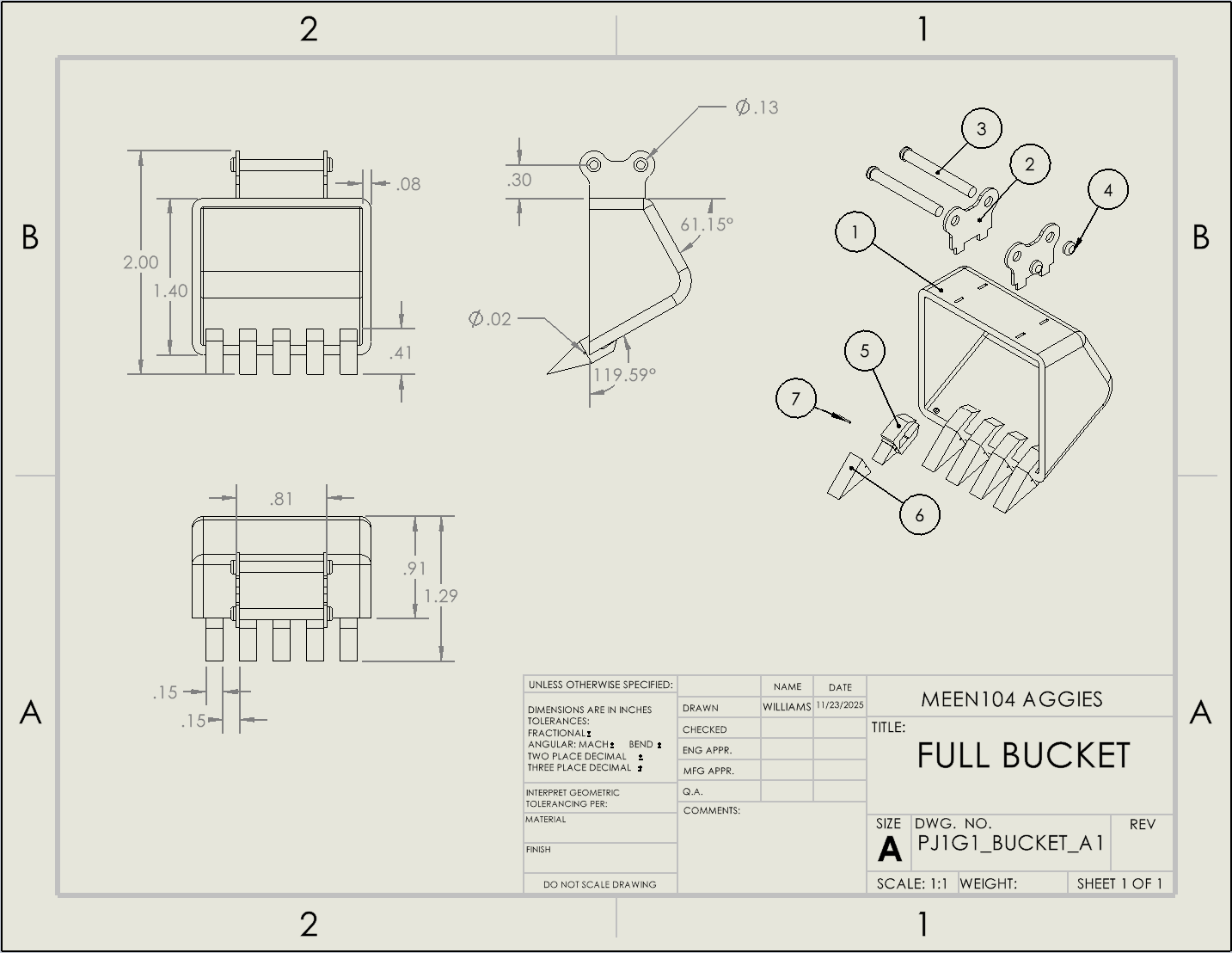
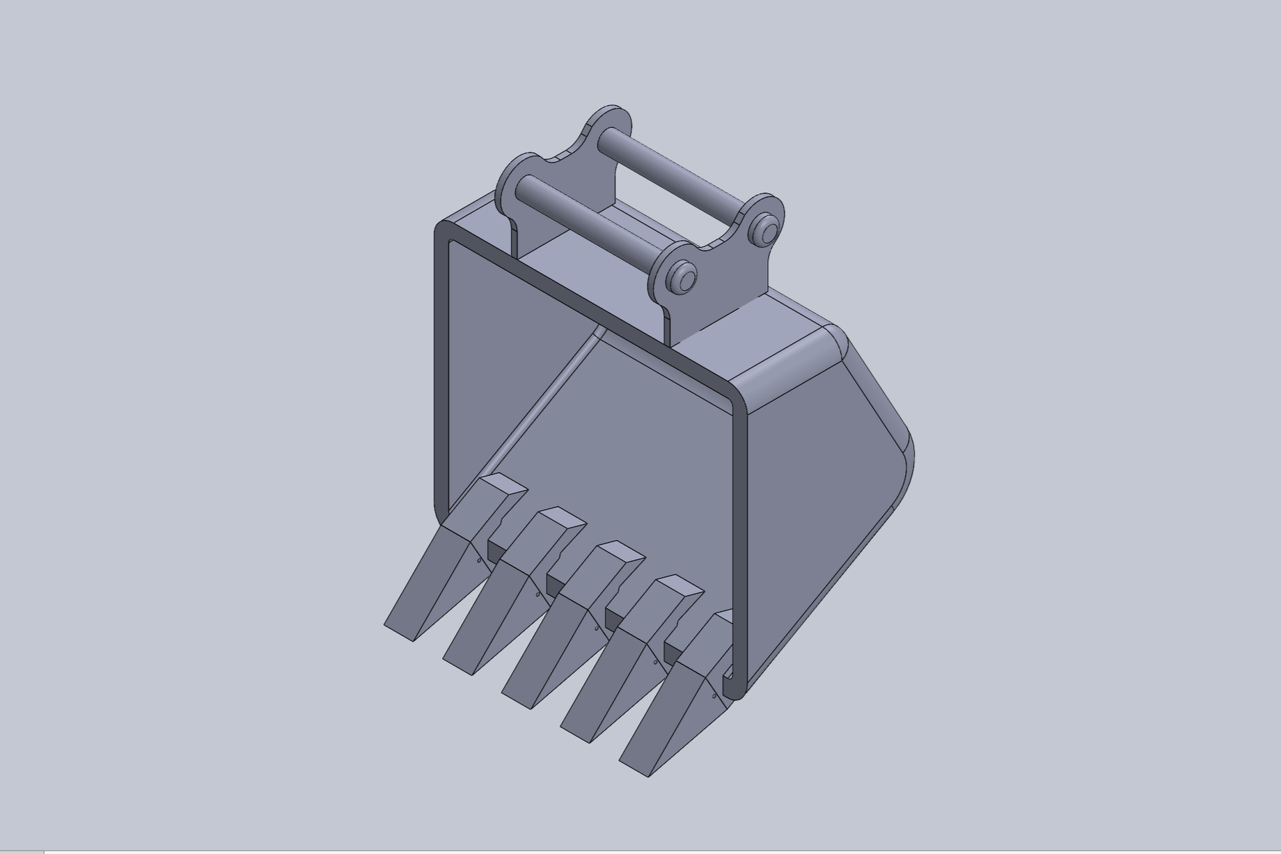
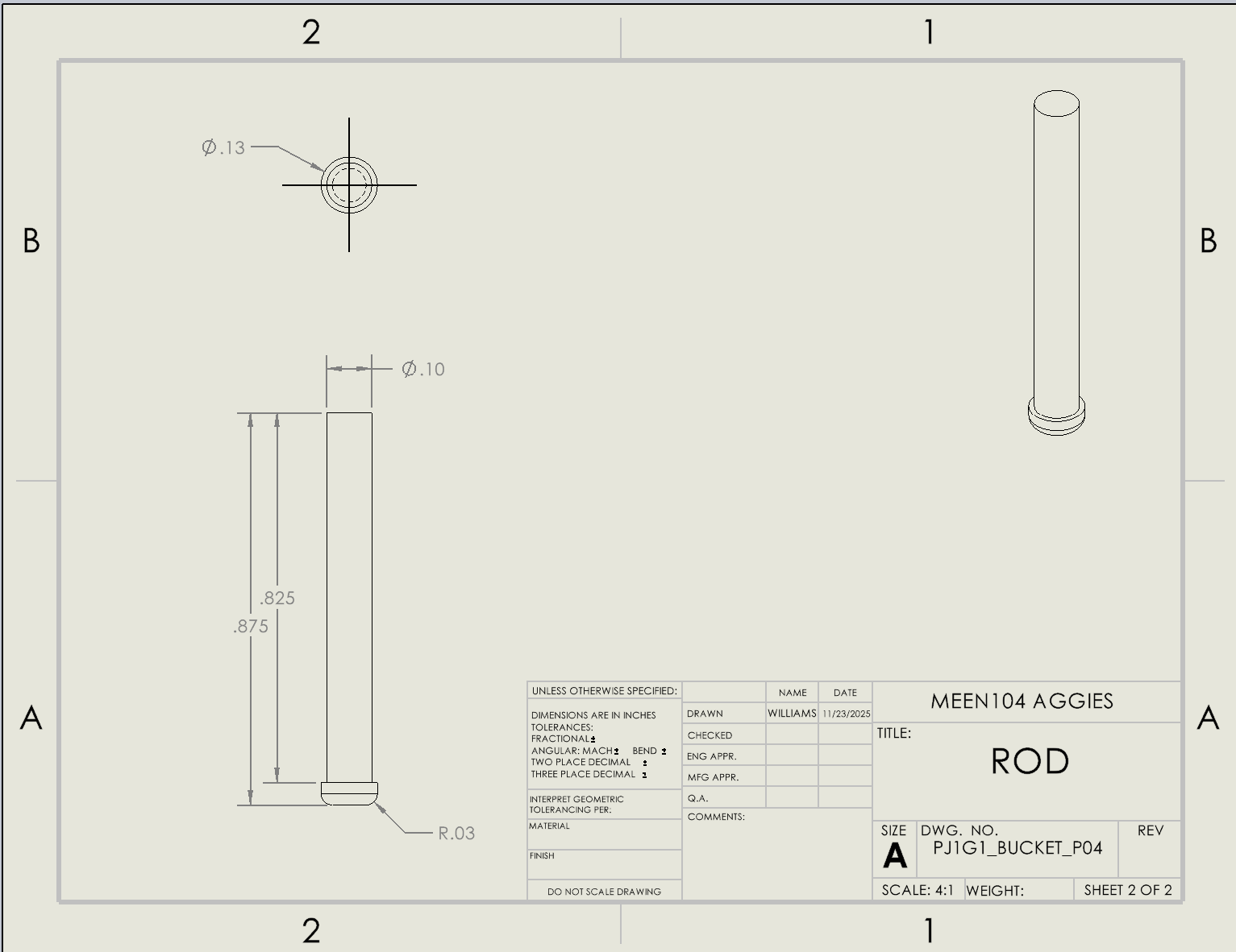
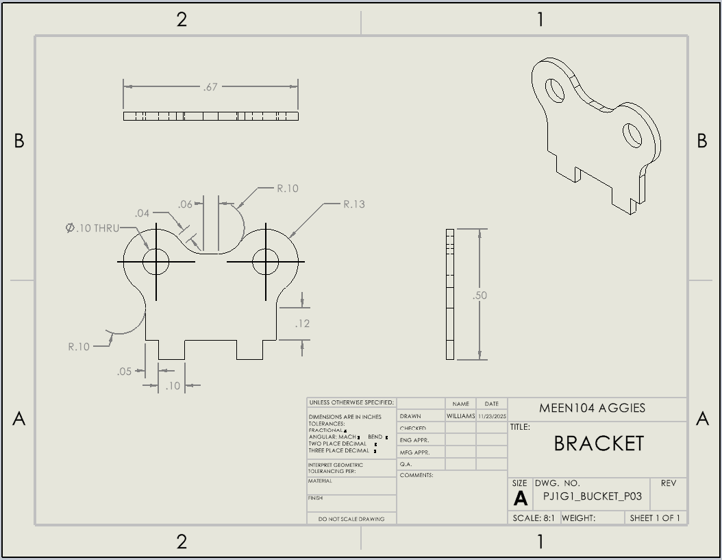
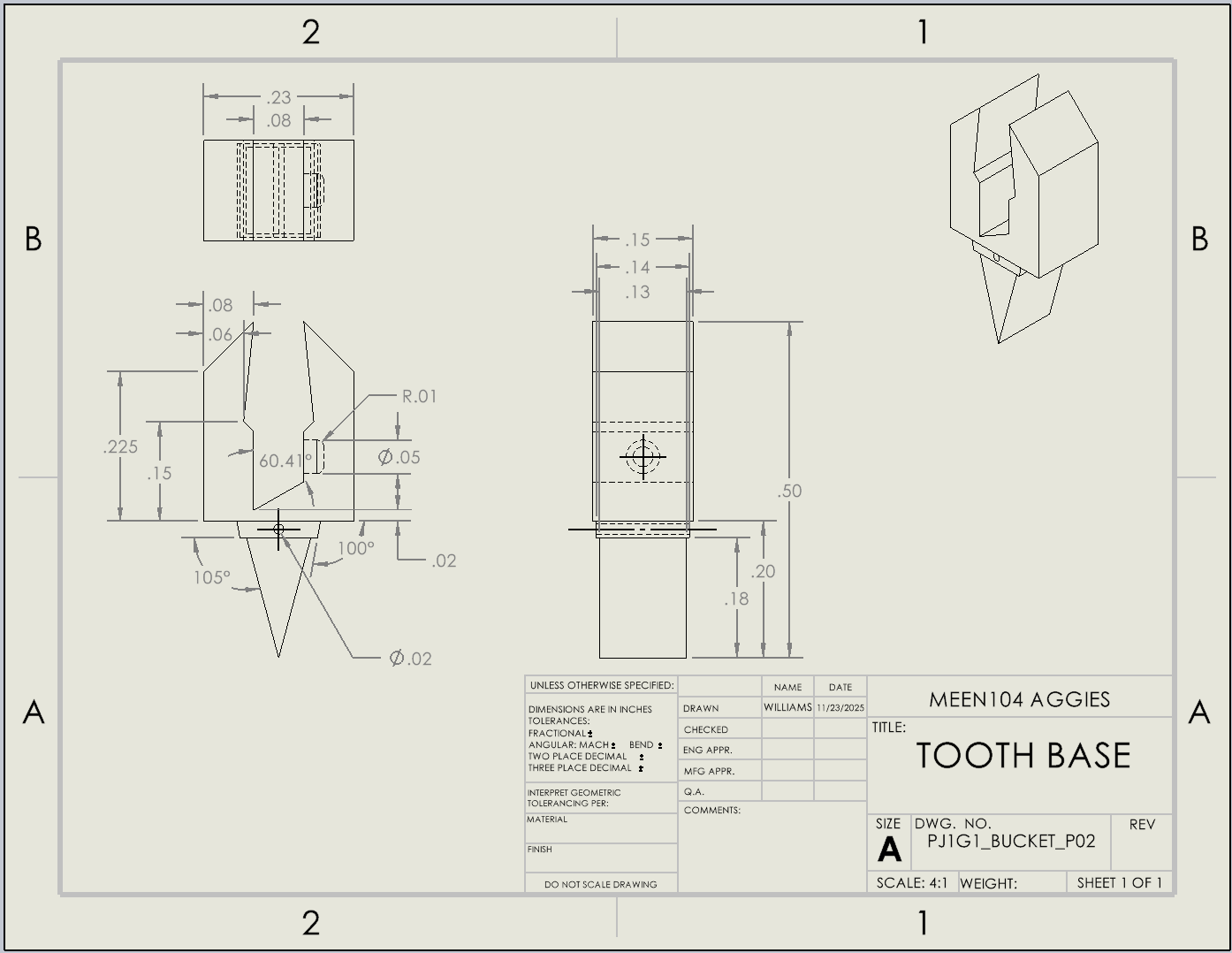
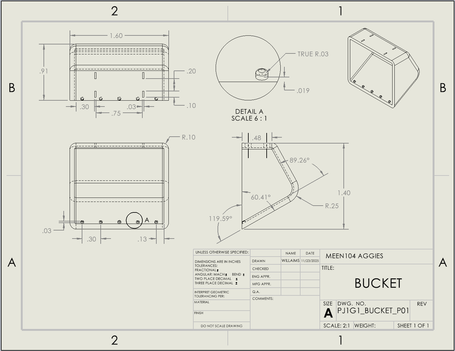
Toy Excavator Arm Assembly (SolidWorks)
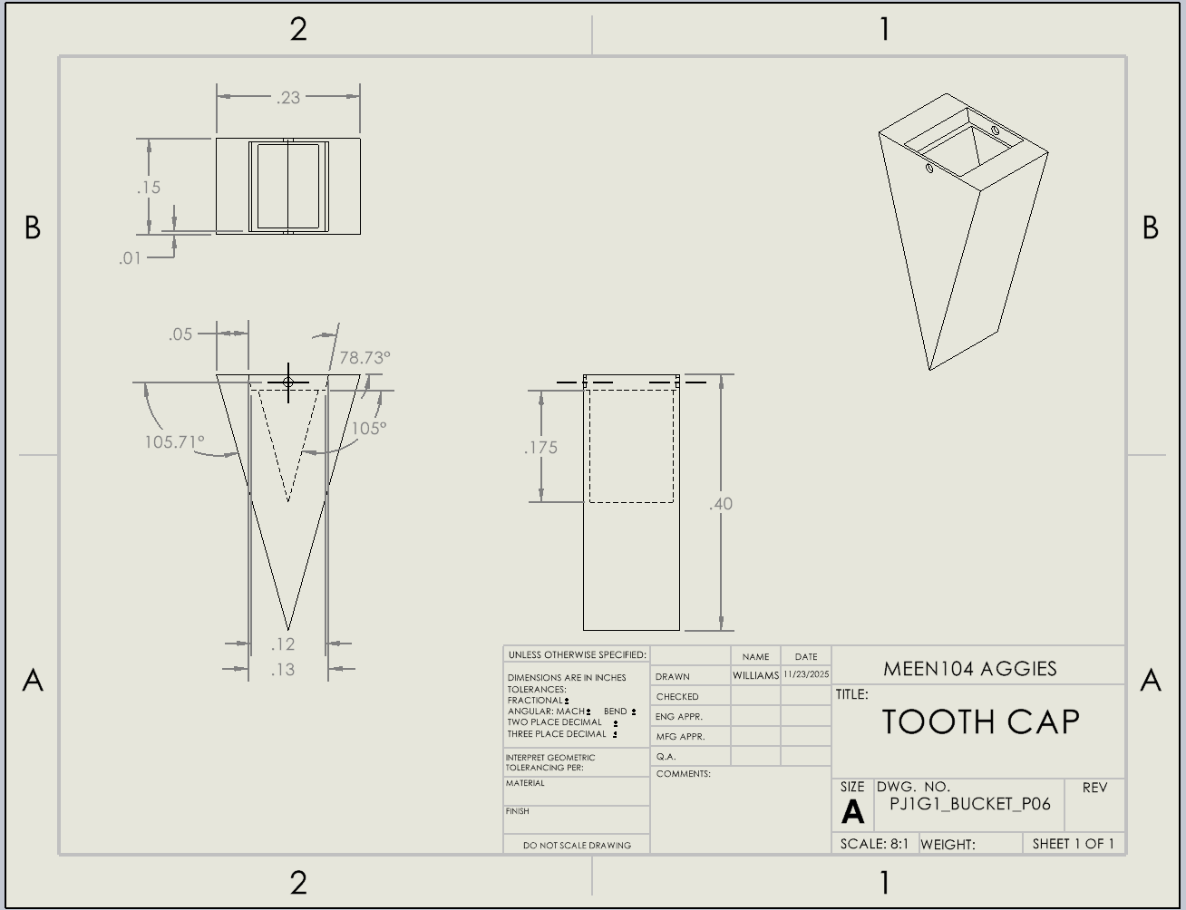
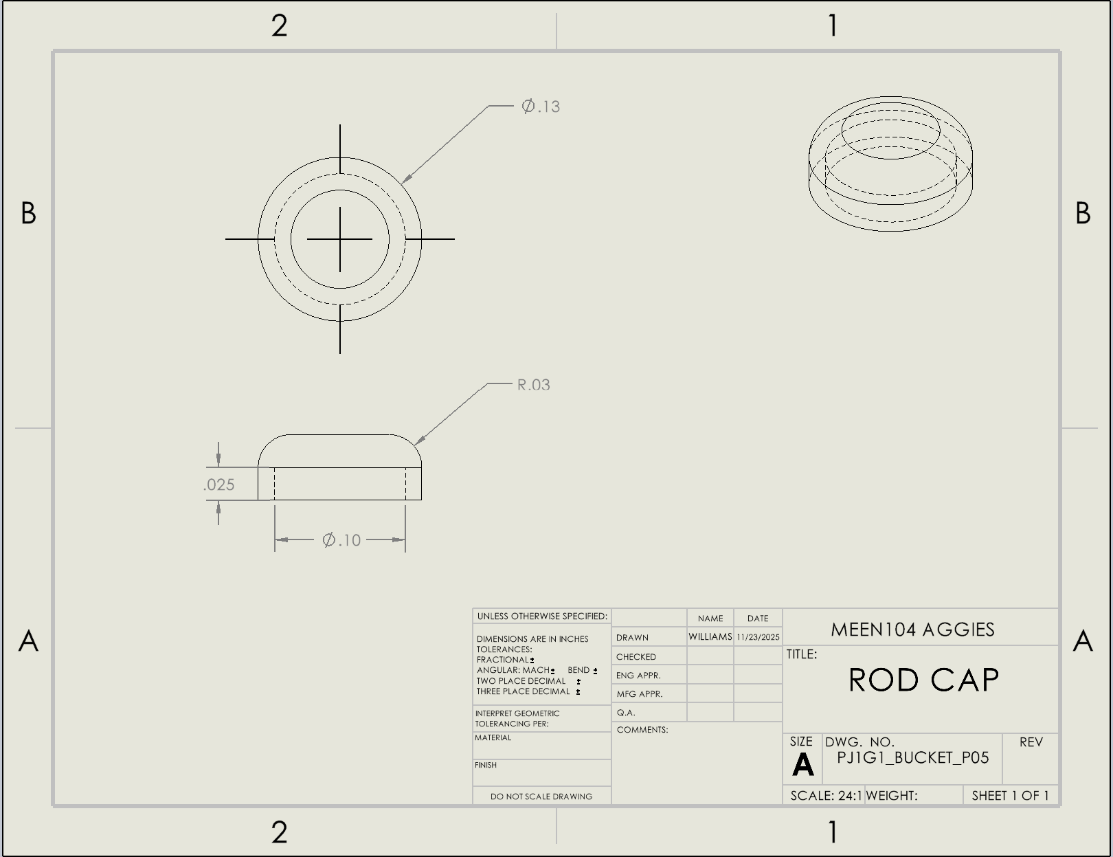
Designed and modeled a toy-scale excavator bucket assembly using SolidWorks
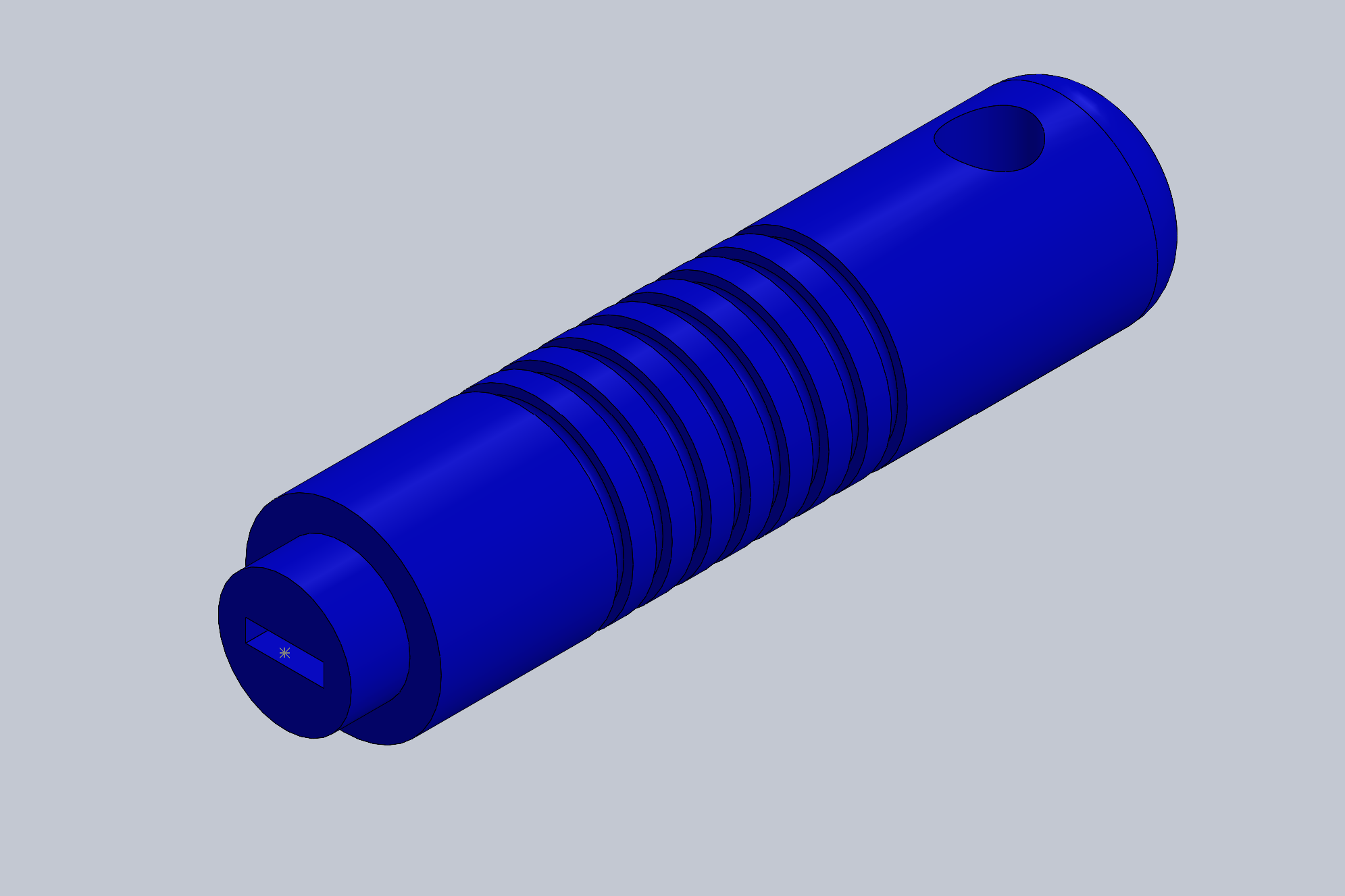
Created individual components including bucket body, linkage arms, and pins
Built a fully constrained assembly to simulate mechanical linkage motion
Produced detailed engineering drawings with dimensions and tolerances
Applied parametric modeling and design for manufacturability principles
Strengthened understanding of mechanical systems and motion transfer
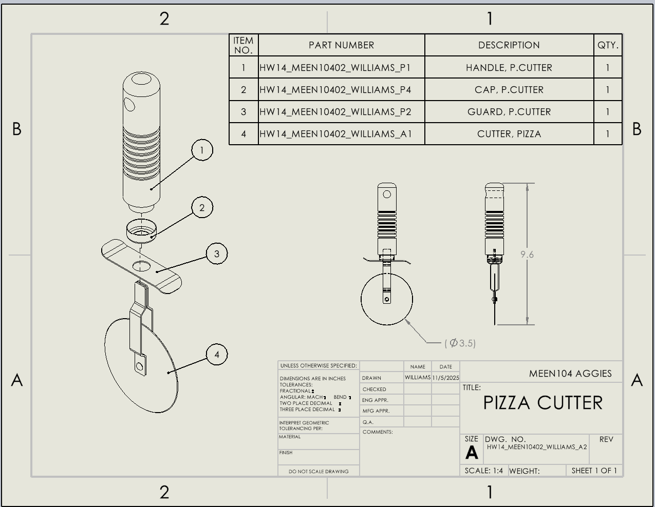
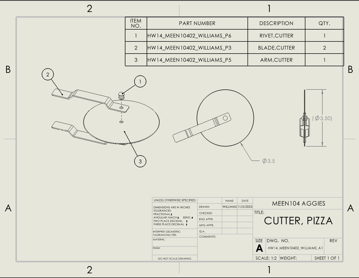
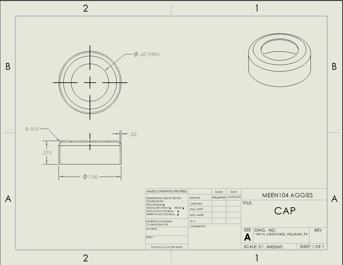
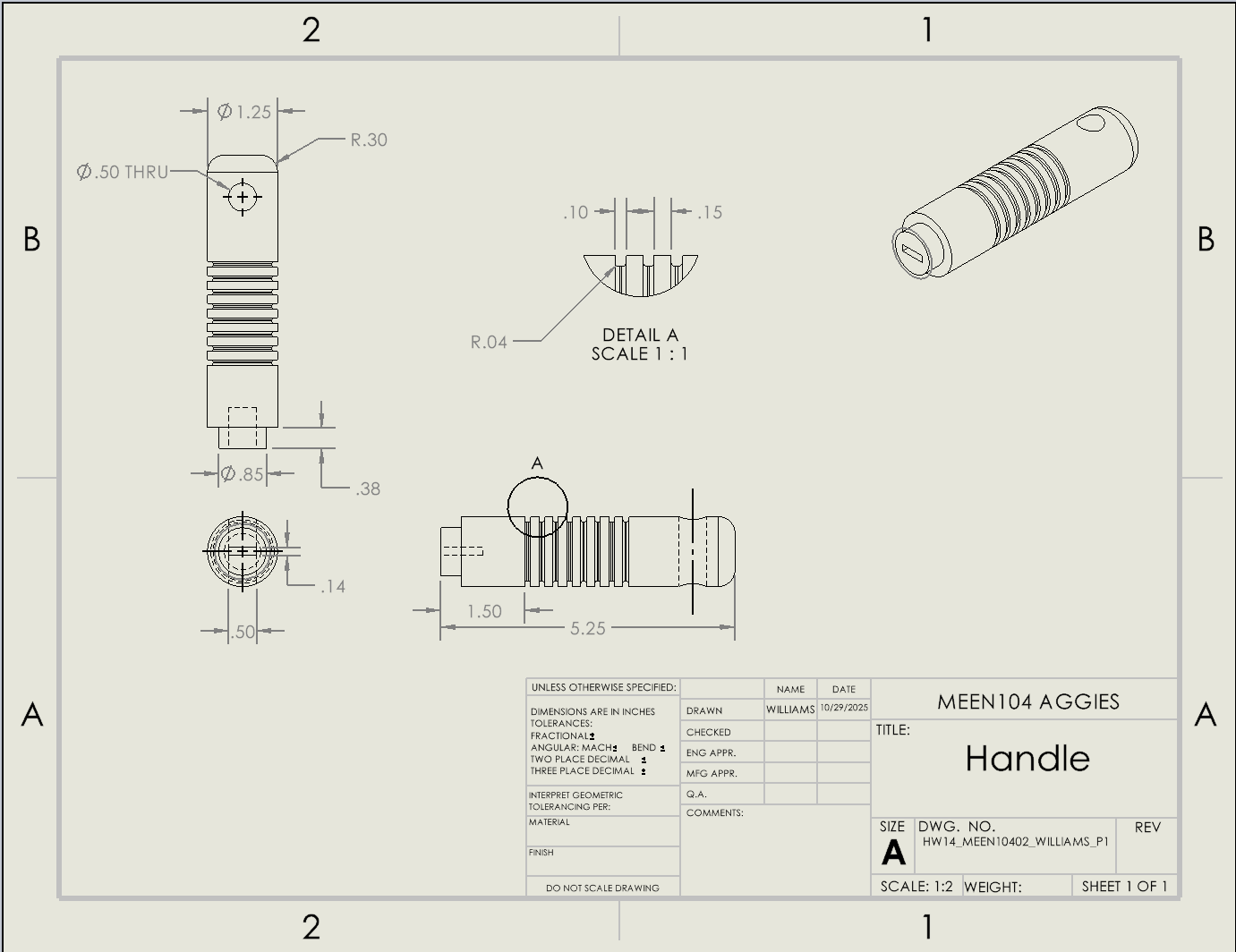
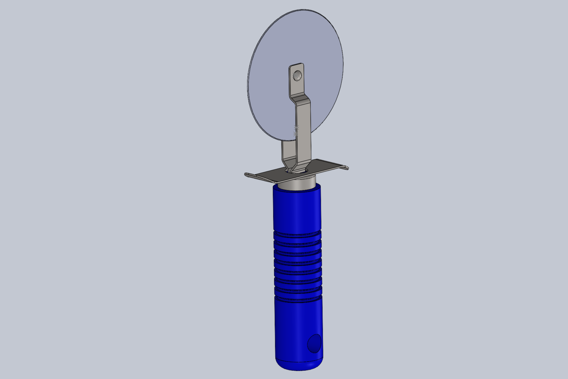
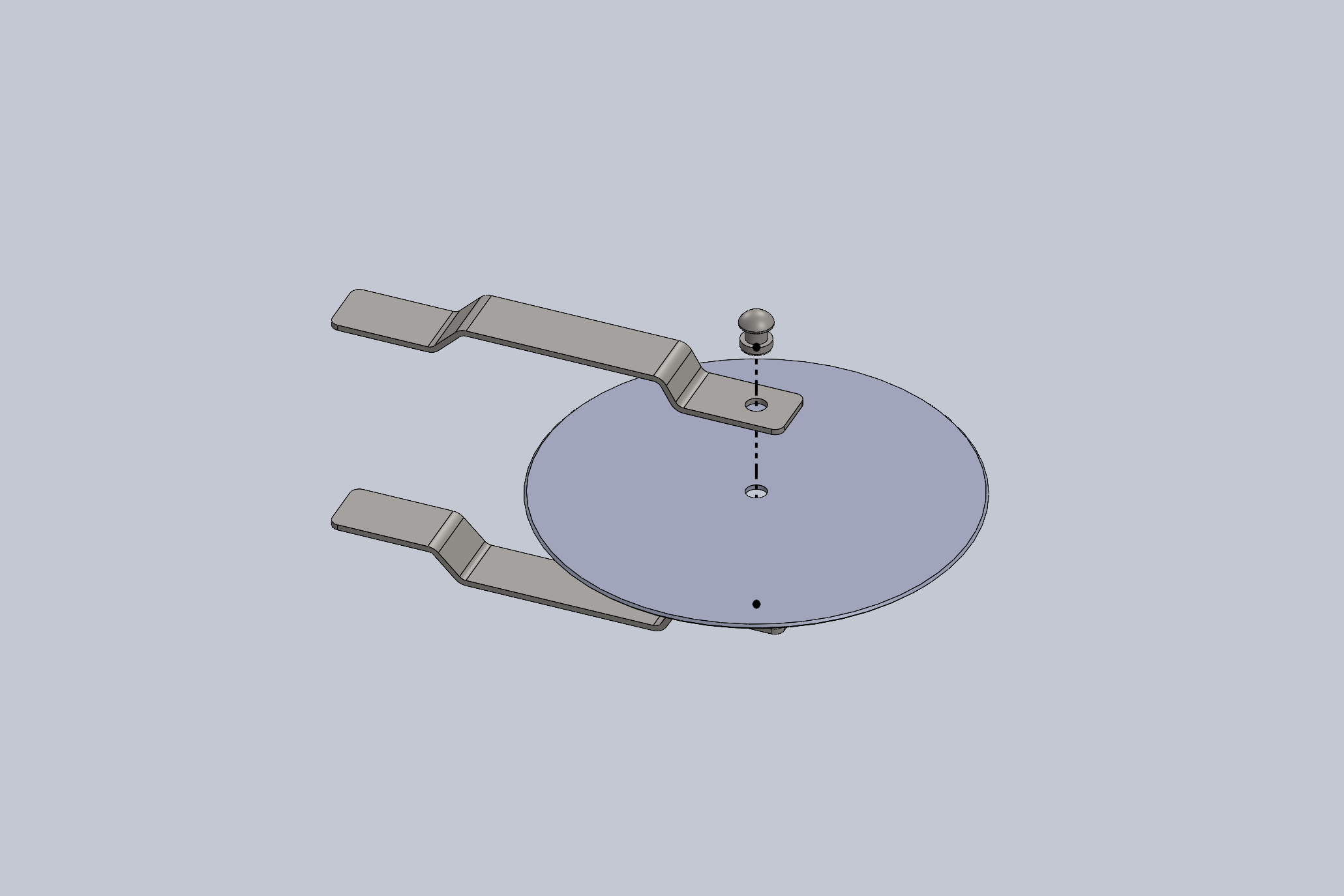
Pizza Cutter Assembly (SolidWorks)
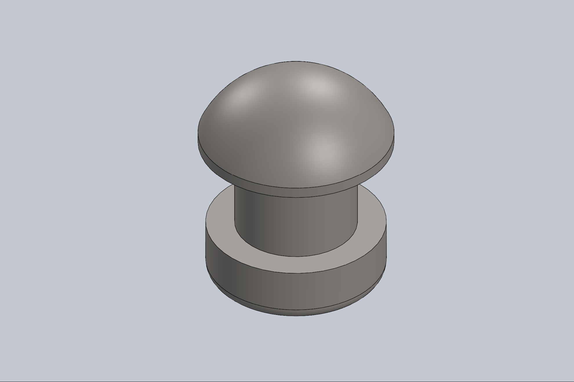
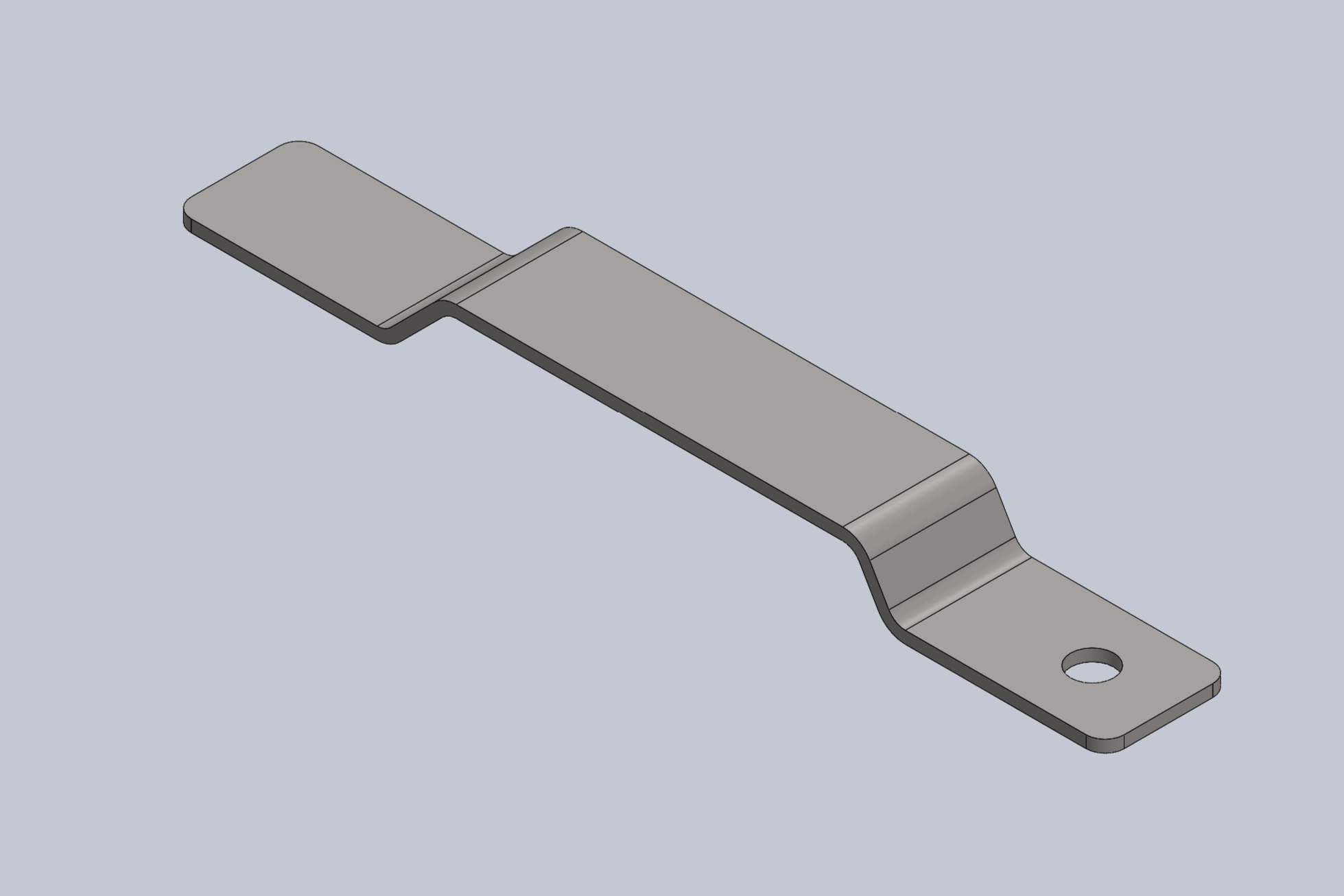
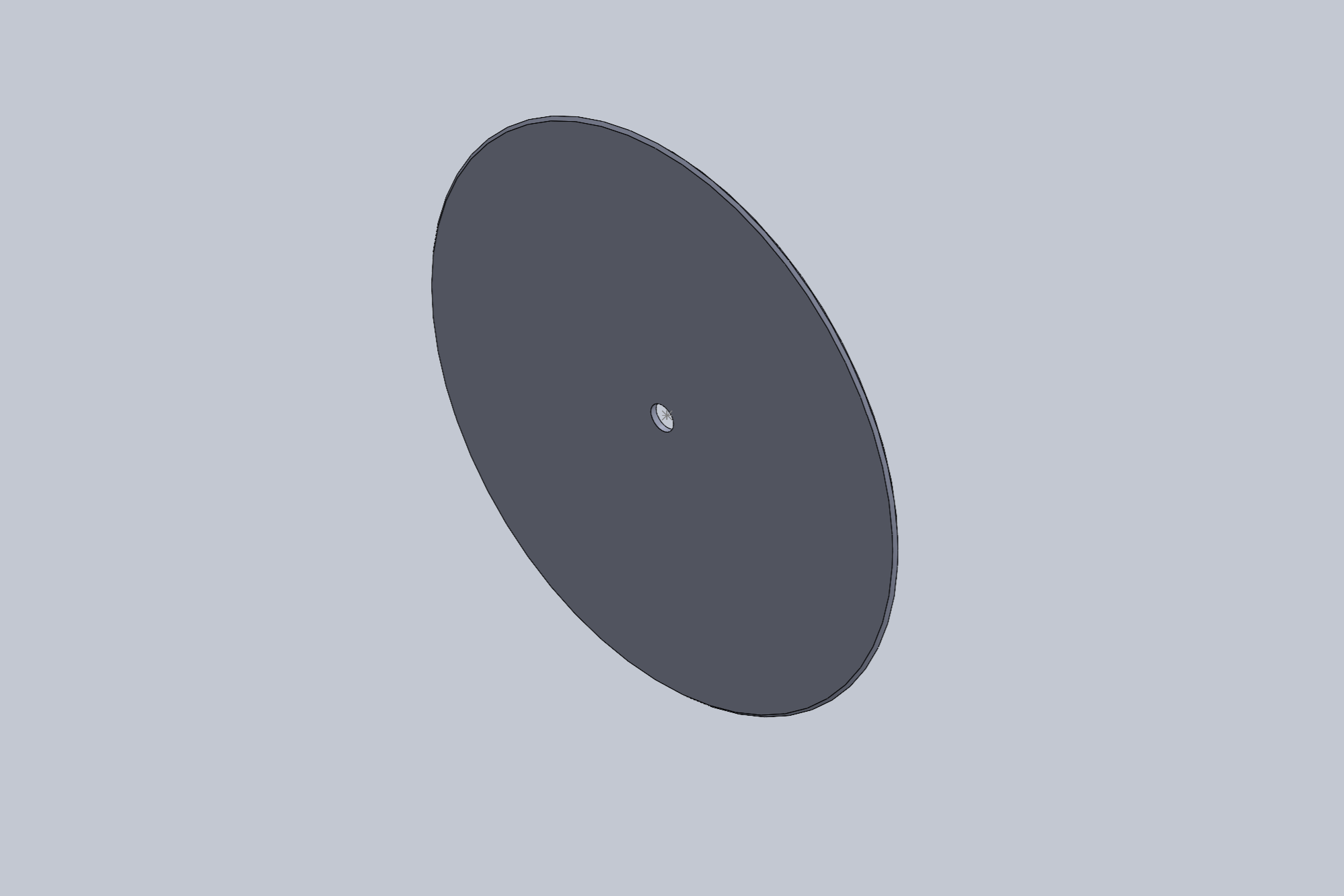
Modeled and designed all individual components of a pizza cutter, including handle, guard, cap, and cutting wheel
Created a fully assembled model using mates and constraints to ensure proper alignment and motion
Applied parametric modeling techniques to maintain consistency across parts
Developed detailed engineering drawings with dimensions, annotations, and bill of materials (BOM)
Designed components with consideration for fit, function, and manufacturability
Strengthened understanding of part-to-assembly relationships and mechanical design
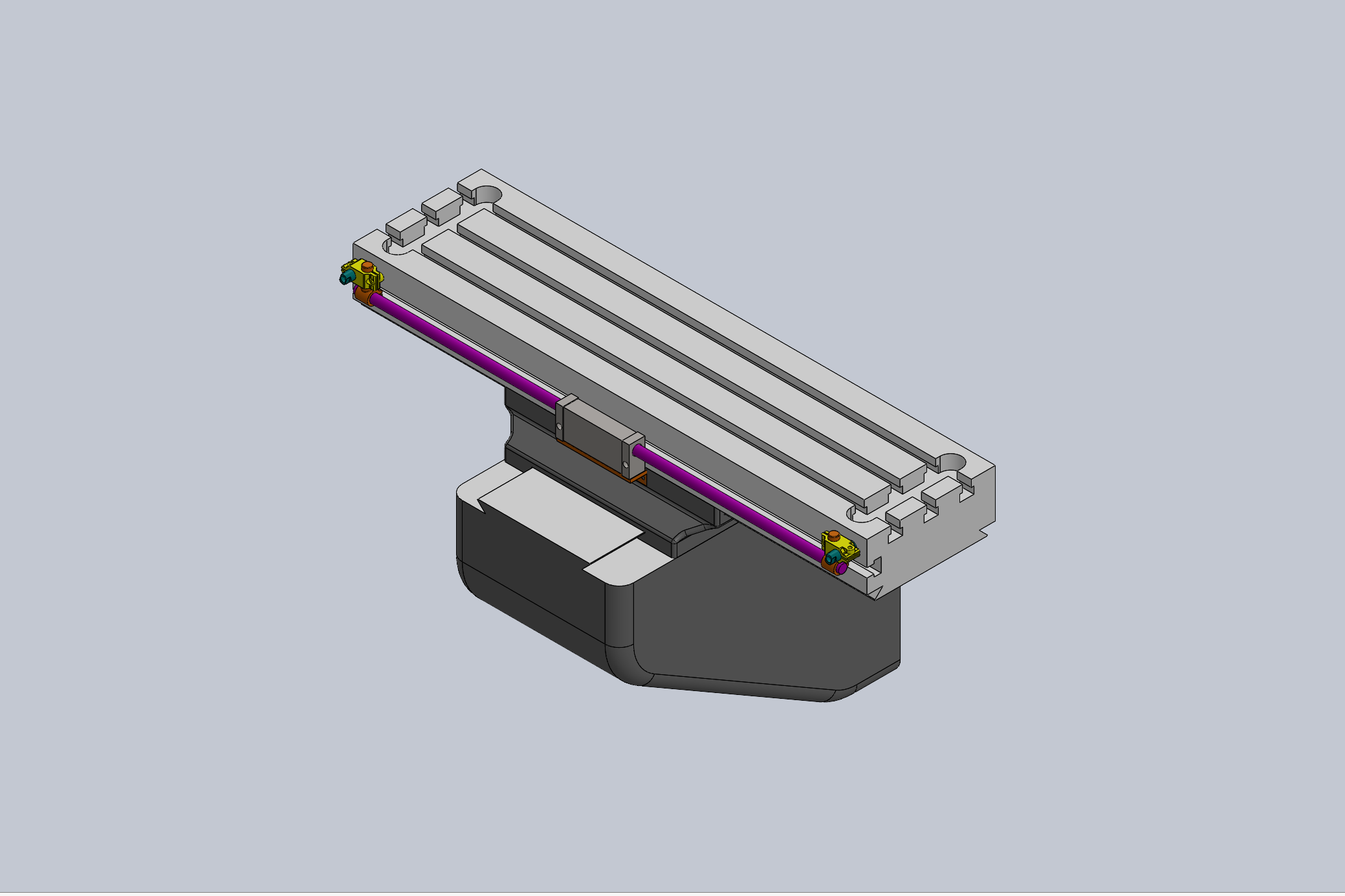
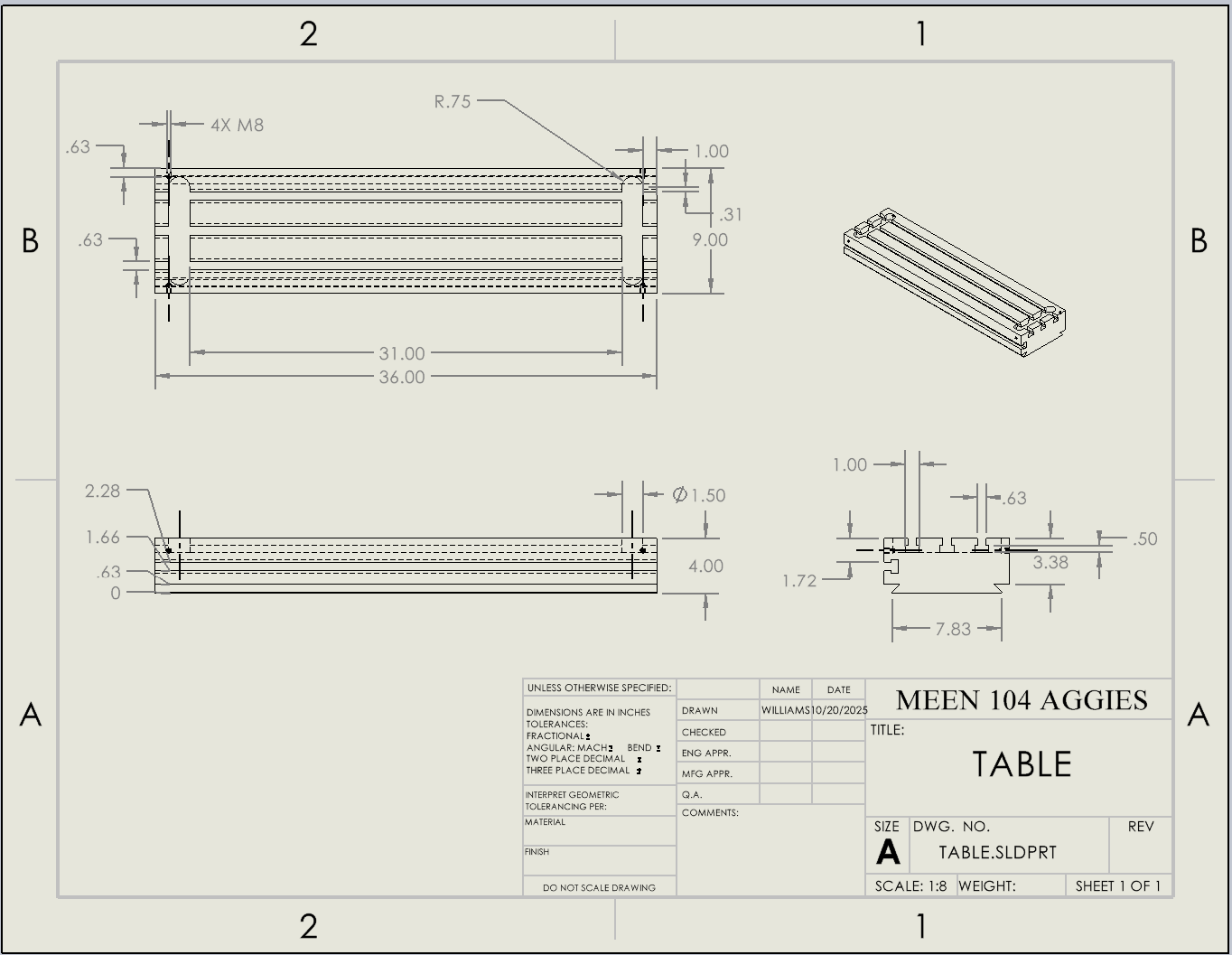
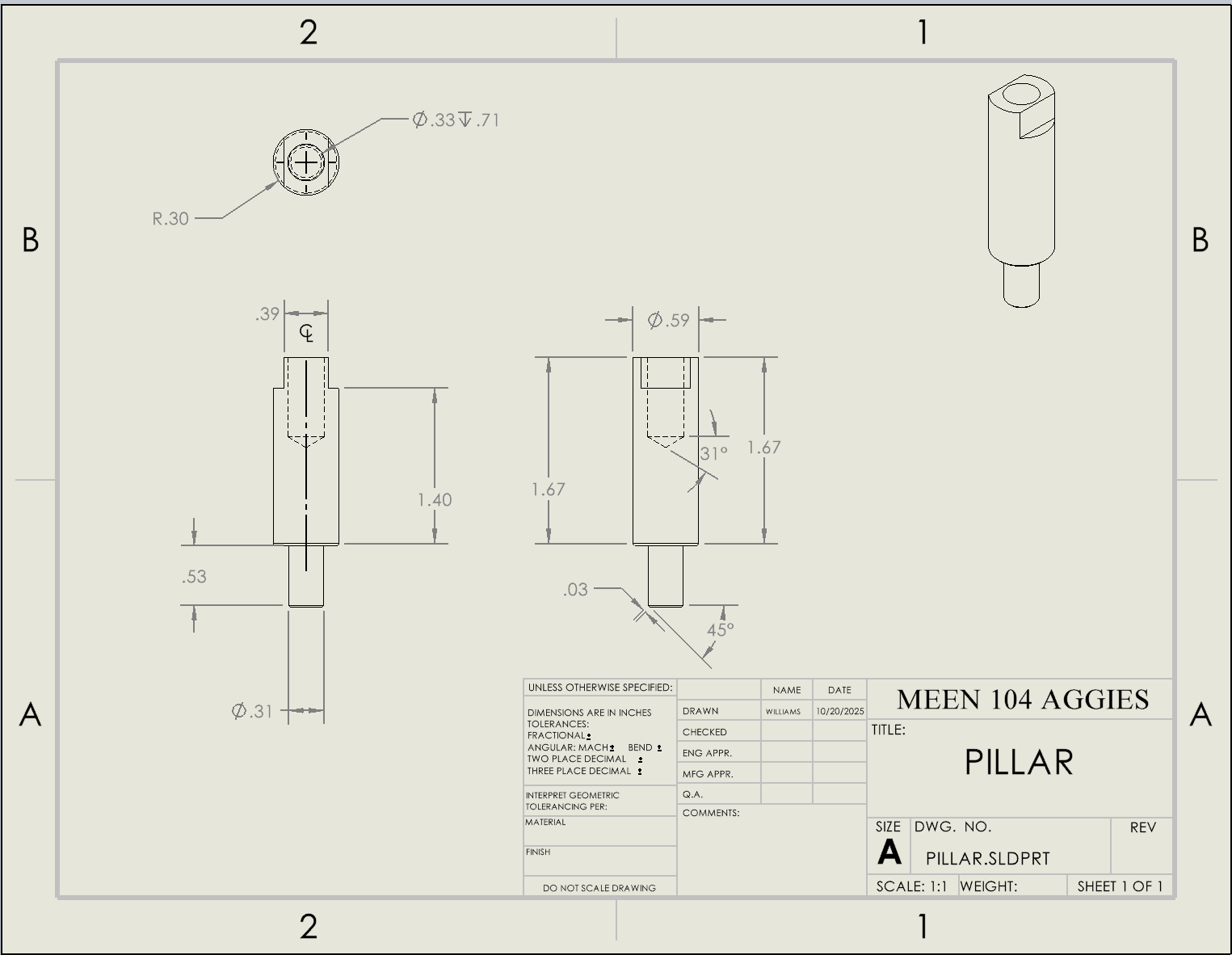
Mechanical Assembly from Engineering Drawings (SolidWorks)
Built a complete assembly in SolidWorks using provided engineering drawings and part specifications
Interpreted 2D technical drawings to accurately model and position components
Applied mates and constraints to ensure proper alignment and functional relationships between parts
Integrated multiple components into a fully defined assembly, maintaining dimensional accuracy
Strengthened understanding of reading engineering drawings and translating them into 3D models
Demonstrated ability to follow design intent and assembly requirements in a structured workflow
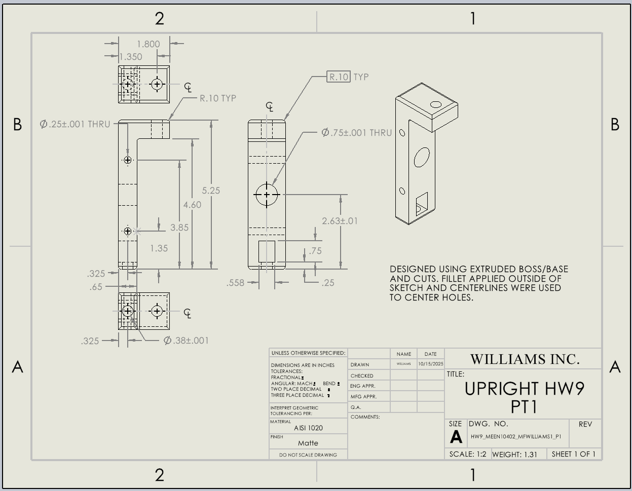
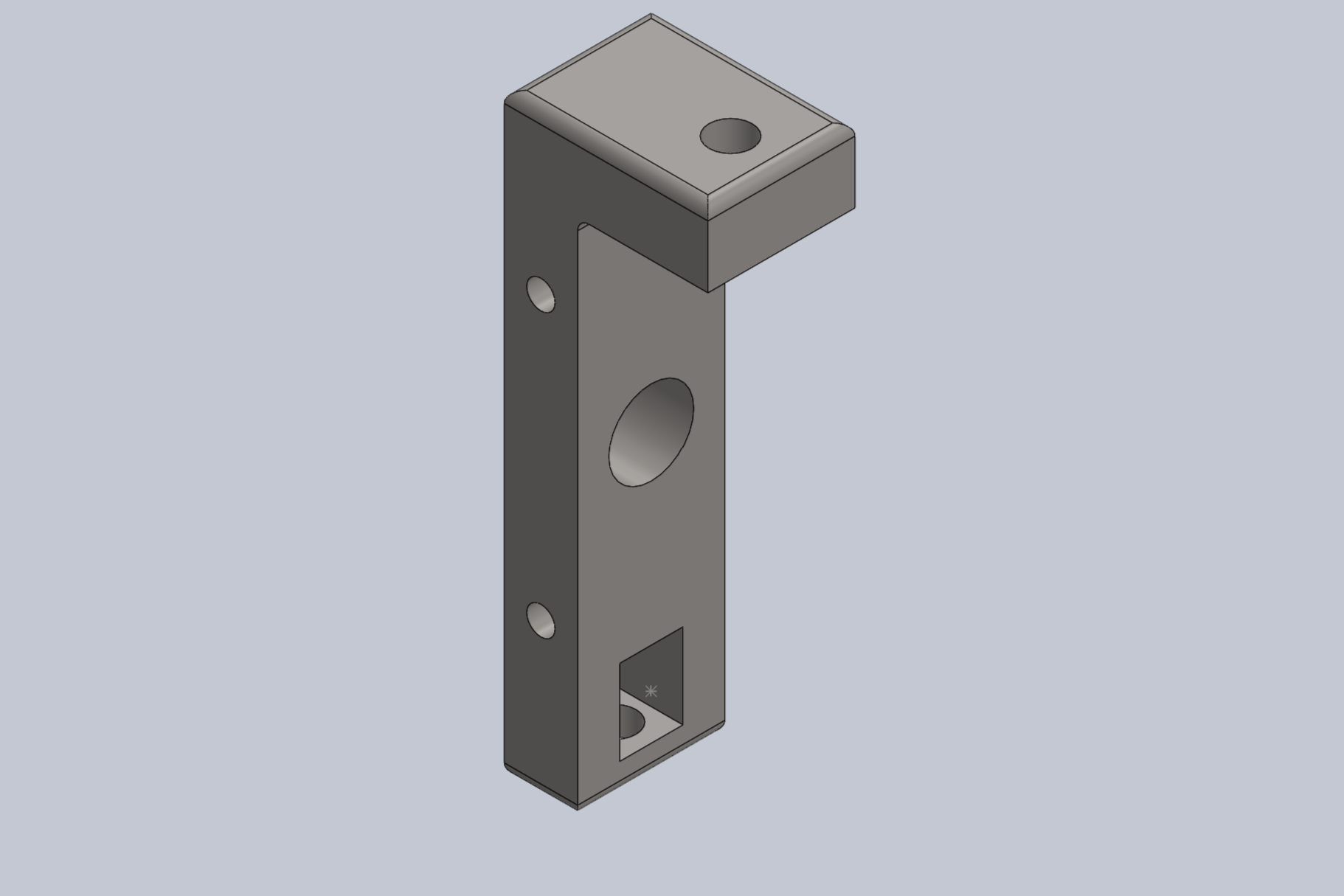
Upright Component Modeling (SolidWorks)
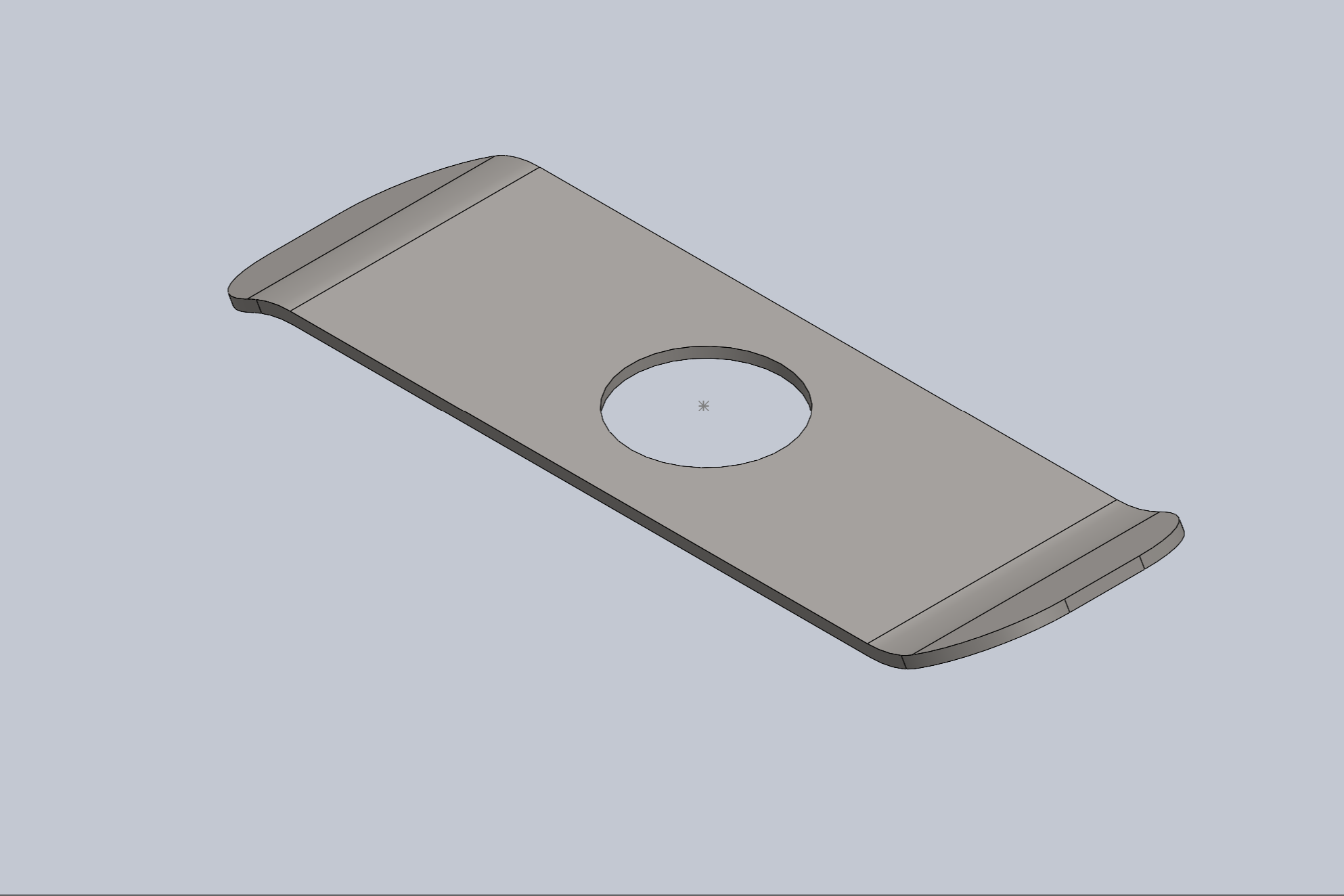
Modeled a mechanical upright component in SolidWorks using detailed engineering drawings
Interpreted dimensions, tolerances, and annotations to ensure high accuracy
Utilized features such as extruded boss/base, cuts, fillets, and hole tools to build the part
Applied centerlines and reference geometry for precise hole placement and alignment
Maintained dimensional accuracy while following engineering drawing standards
Strengthened ability to translate 2D technical drawings into fully defined 3D models
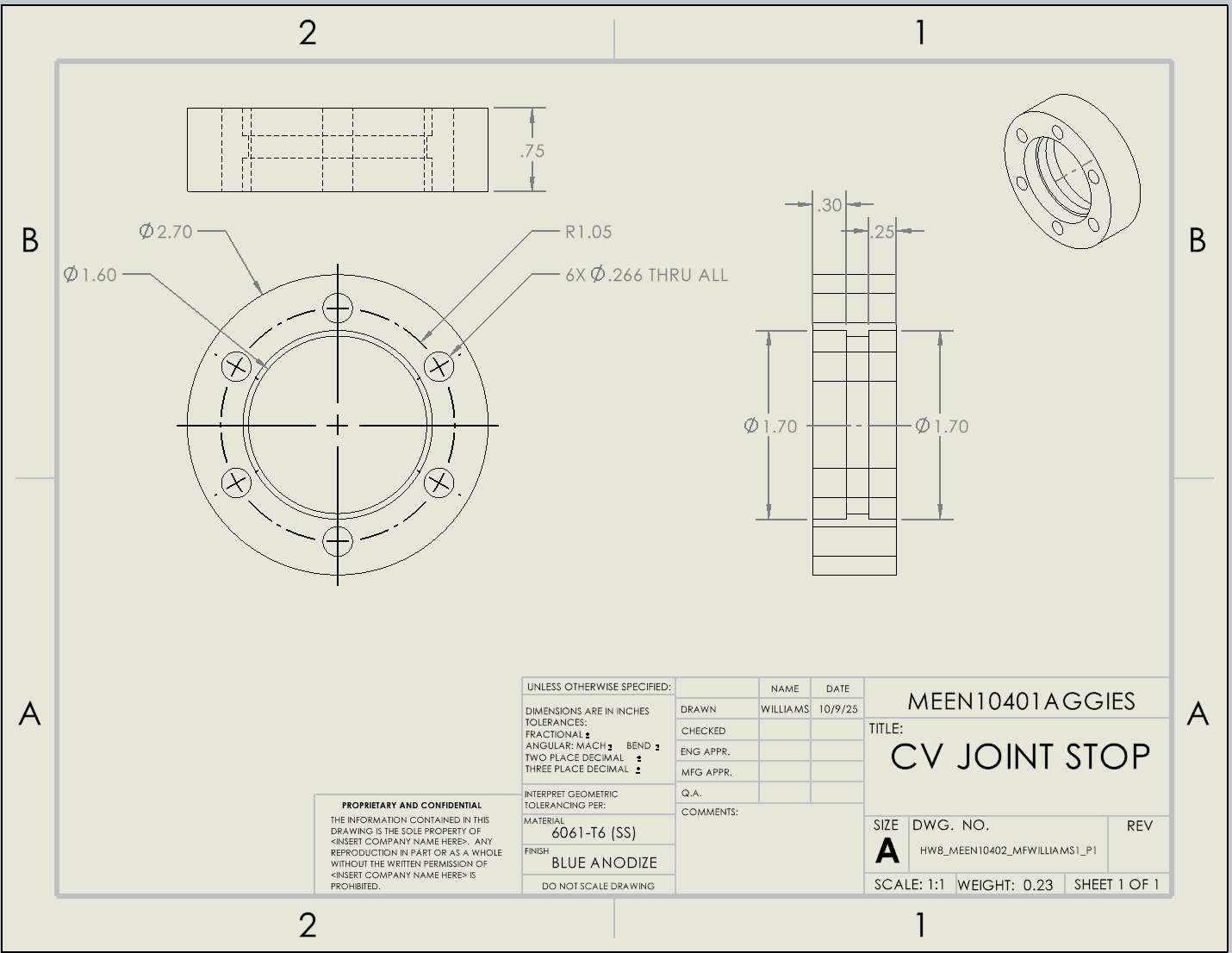
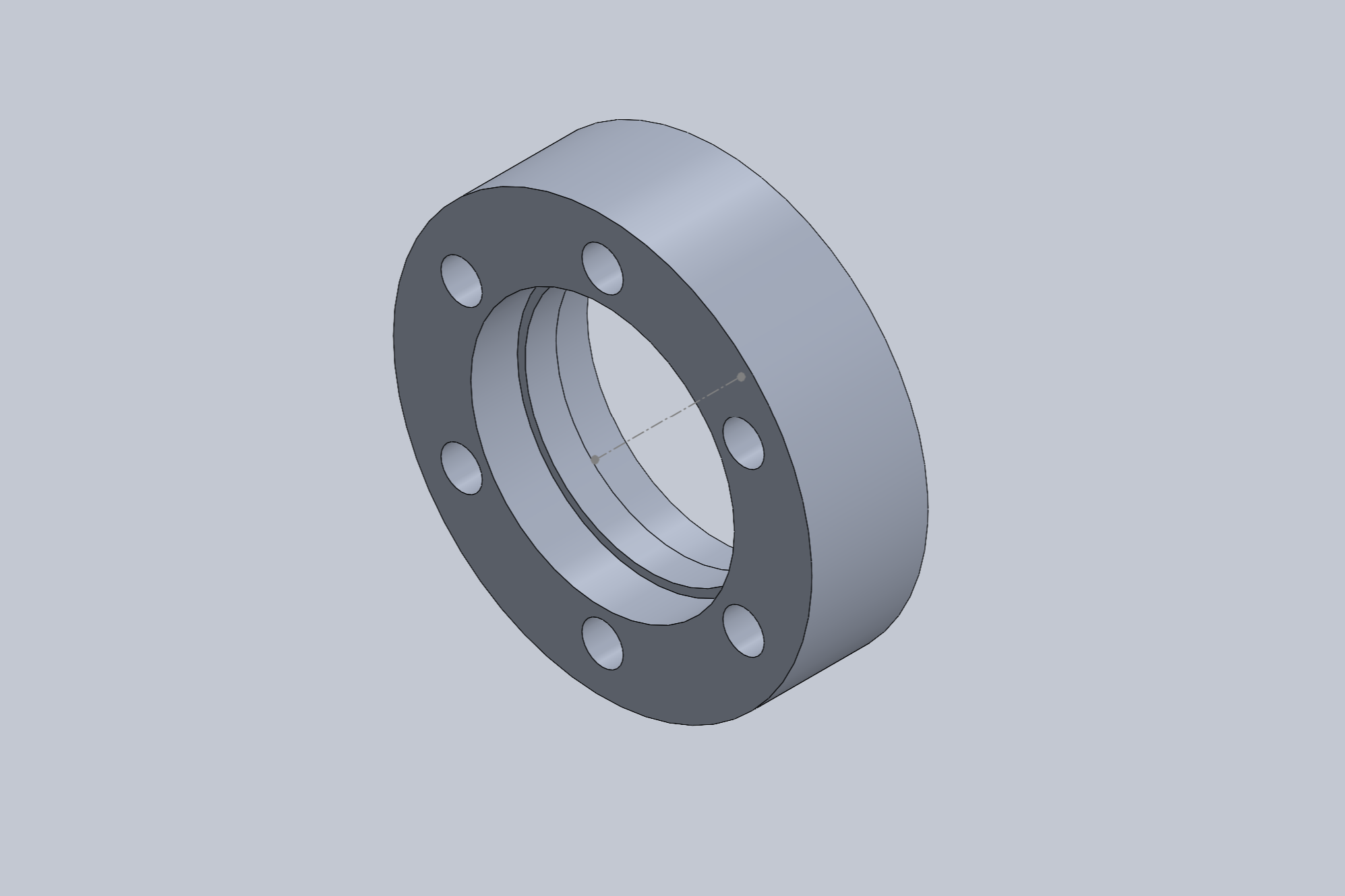
CV Joint Stop Component (SolidWorks)
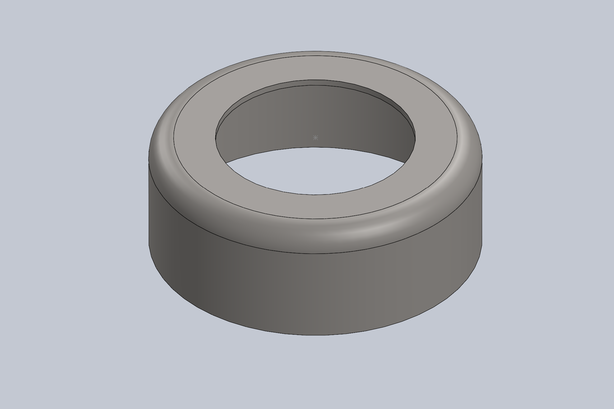
Modeled a CV joint stop component in SolidWorks using detailed engineering drawings
Interpreted dimensions, tolerances, and circular geometry to ensure precise design
Created concentric features using extruded boss/base and cut operations
Applied circular patterning to accurately position multiple holes around the component
Utilized reference geometry and centerlines to maintain symmetry and alignment
Ensured dimensional accuracy and design intent throughout the modeling process
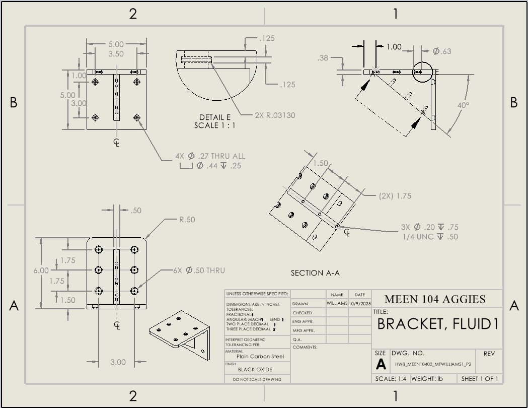
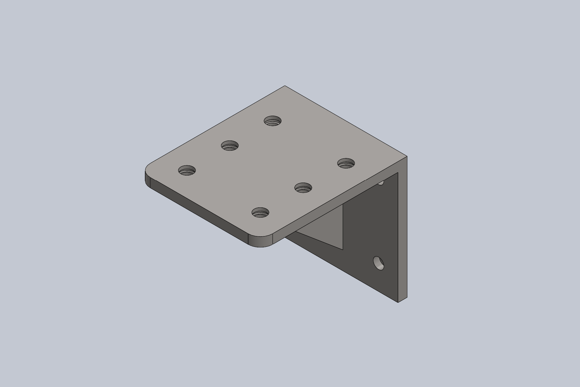
Bracket Component (SolidWorks)
Developed a fully defined 3D model of a bracket component in SolidWorks from complex engineering drawings
Interpreted section views and detailed annotations to accurately capture internal and external features
Implemented patterned hole features, threaded holes, and counterbore specifications
Applied parametric modeling techniques to maintain consistency and allow design modifications
Ensured alignment with design intent, symmetry, and manufacturability constraints